Israel Defence Forces M247 DIVADS

Jakko

Way past the mad part
SMF Supporter
Joined
Apr 28, 2018
Messages
10,793
Points
113
First Name
Jakko
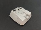
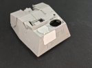
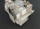
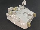
The hull is now almost completely built per the instructions:
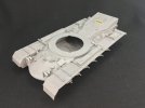
IMG_0599.jpegIMG_0600.jpeg

The only things missing are the wheels and track, the air cleaners (which go in the empty spaces on the mudguards) and a few other bits that I think the Israelis would have removed or fitted elsewhere. The air cleaners in the kit are the later top-loading type, that was also used on the M48A5 and M60A3, but going by photos, the Israelis seem to have kept using the older, side-loading type from the M48A3, M60 and M60A1 (and which they also fitted to their Centurions). So now I need to either modify the kit parts, or find acceptable side-loading ones somewhere.

When building this kit, and presumably Takom’s M48A3 and -A5, beware that the supports for the mudguards are all a very tight fit. Most will want to go in eventually with careful pressure and liquid cement, but both H13s (the ones behind the air cleaners) still won’t. The slots for them are simply too narrow, which is a bit odd because H12 (in front of the air cleaners) looks to be exactly the same as H13 but will fit in its own location — but also not in that of H13. I widened the slots on one mudguard by scraping with a knife, while on the other side, I filed down the tabs on H13 slightly. Both methods work, but filing was much quicker and easier, so I would recommend that.
 

Jakko

Way past the mad part
SMF Supporter
Joined
Apr 28, 2018
Messages
10,793
Points
113
First Name
Jakko
In my Patton spares box, I found side-loading air cleaners from the Tamiya M60A3 kit I built around the turn of the century, because that kit also has the newer top-loading ones you’re supposed to use instead. These may be crude by modern standards, but the basic shape is good. After sawing off the lumps that represent the inlet pipes and filing the front faces flat, I detailled them with plastic card, rod, strip, and punched bolts:

IMG_0601.jpeg

I also rebuilt the hinges, because the parts have them the wrong way around. For reference, I used this picture I took in 2000 of the M103A2 heavy tank in Bovington:

m103a2aircleaner.jpeg

Attached to the model:

IMG_0602.jpeg

All I needed to do here was remove the rear locating ridges.

I also started on the turret:

IMG_0603.jpeg

I’ve said it before, and Takom does it again here: they want you to fit all kinds of small bits to large parts before adding those large parts together. Therefore, I immediately deviated from the suggested sequence :smiling3:

Incidentally, in step 29, Takom says to put part R13 between the lower turret part and the elevating bit. This is a travel lock, and if you want the guns movable, fit R13 downward instead, so it fits into lug R9 that’s installed in step 27.
 
Last edited:

Jakko

Way past the mad part
SMF Supporter
Joined
Apr 28, 2018
Messages
10,793
Points
113
First Name
Jakko
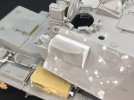
Until yesterday, I had never realised that the M247’s turret had a rear door for the gunner. However, I figure that it would get rather in the way for putting external stowage on the vehicle, so perhaps the Israelis would have modified the turret by welding up the door and putting a roof hatch in.

IMG_0604.jpeg

The hatch is a leftover from a Hobby Boss M706 Commando armoured car kit, where it was unused. I had to file it down a bit so it wouldn’t look like it’s just completely on top of the turret. I copied the door shape onto 0.5 mm plastic card, as this was simpler than taking all of the details off the door and filling the hole for a vision block in the middle of it.

I also had to get the left rear periscope by the commander’s hatch out, because with the hatch in place it wouldn’t have much of a field of view. That was fun, I ended up wiggling it back and forth for quite a while until the glue finally gave way. I then fitted it back in from below, but upside-down so that more of it sticks up above the turret roof.
 

Scratchbuilder

SMF Supporter
Joined
Jul 2, 2022
Messages
1,938
Points
113
First Name
Mike
More and more, this is getting exciting.... How about a stoeage cage on the rear of the turret, hence the welded up gunners hatch...
 

Jakko

Way past the mad part
SMF Supporter
Joined
Apr 28, 2018
Messages
10,793
Points
113
First Name
Jakko
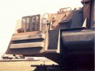
That is precisely the intention, yes :smiling3: The M247 has this very obvious shelf right under the door:

DBB9B7F4-8710-40CF-AF0C-D6763CCFD2CC_1_105_c.jpeg

I would be highly surprised if crews didn’t want to use that for stowage. As it was, though, all that was on there is those two laundry baskets that appear to have held 7.62 mm ammo cans, two side-by-side, and probably two layers, in each.¹ But weld up the door and put some bars across …

¹ Which in itself makes you wonder: there was one M60 machine gun on the vehicle, yet it had three of these baskets, so that would be twelve plus one (on the gun) is thirteen boxes of machine-gun ammo. How much shooting were they expecting the commander to be doing with that M60?
 

Jakko

Way past the mad part
SMF Supporter
Joined
Apr 28, 2018
Messages
10,793
Points
113
First Name
Jakko
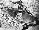
The US Army always had an obsession with machine guns — I mean, count the number of them on this M2 medium:

M2_testings_AAmounts_creditsww2photos.se.jpg

Maybe the large number of ammo boxes on the M247 was just the early-1980s manifestation of that :smiling3:
 

Jakko

Way past the mad part
SMF Supporter
Joined
Apr 28, 2018
Messages
10,793
Points
113
First Name
Jakko
I had to look up who that is, as the name rings a bell but I couldn’t place it. Now I did, yes, maybe he was. It seems to fit right in with the story of the real M247, anyway ;)

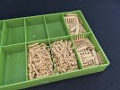
I’ve been removing track links from the sprues. This is all 245 links Meng gives you, and their track pins:

IMG_0606.jpeg

Not cleaned up yet — I still need to remove four attachment points per link …

And some progress on the turret:

IMG_0607.jpegIMG_0608.jpeg

The radars are still loose, so they don’t get in the way too much. I’ll add their covers after spraying the model, as IRL these are usually not to be painted, so to make it easier I’ll just paint them separately and add them afterward.

The filler is where I filled the locating holes for the American smoke grenade launchers and one of the ammo boxes for them. I’ll be installing Israeli ones instead, so these had to go.
 

JR

Member of the Rabble and Pyromania Consultant
SMF Supporter
Joined
May 26, 2015
Messages
17,275
Points
113
Location
lincs
First Name
John
Any help you need on those tracks just say ;)
 

Jakko

Way past the mad part
SMF Supporter
Joined
Apr 28, 2018
Messages
10,793
Points
113
First Name
Jakko
Thanks, but these should be doable :smiling3: You get a jig to put a bunch of links into, so that you can then push a set of pins into all of them at once. Or so the theory goes — I haven’t actually tried assembling any yet …
 

Jakko

Way past the mad part
SMF Supporter
Joined
Apr 28, 2018
Messages
10,793
Points
113
First Name
Jakko
Progress on the turret:

IMG_0614.jpeg

I filled the mounting holes for all the stowage racks on the right side of the turret, because it seems to be the only place where you can reasonably fit a Stinger missile launcher, but I doubt the crew would want their sleeping bags burned to a crisp and blown off the vehicle every time they launch a missile. This also neatly justifies adding a stowage rack to the back of the turret, of course.

On the air cleaners, I removed the clasp because somebody asked why I used the old models instead of the Israeli armoured ones. On investigating, I found the Meng Magach kit has the unarmoured ones but without a clasp (and plus two bolts that I still need to add here), so I decided to go for that style.

The track links are now all cleaned up, but still need to be assembled:

IMG_0617.jpeg
 

Jakko

Way past the mad part
SMF Supporter
Joined
Apr 28, 2018
Messages
10,793
Points
113
First Name
Jakko
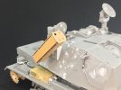
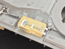
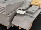
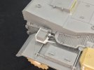
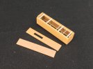
With the Nike now base-painted, I’ve turned my attention back to the M247. At which point I discovered that I had glued the infantry telephone on back to front :sad: Of course, now the glue had had several weeks to dry, cutting it off from its shelf to simply turn it around proved impossible, so I ended up cutting off the shelf and making a new one:
IMG_0829.jpeg

I also added some extra detail to the phone box, mainly the missing edges of its lid, as well as the cable protector that runs from the box to the tank’s hull:

IMG_0831.jpeg

This based on the pictures I took of Bovington’s M60 some 24 years ago, which has the same type of infantry telephone.
 

Jakko

Way past the mad part
SMF Supporter
Joined
Apr 28, 2018
Messages
10,793
Points
113
First Name
Jakko
I’ll make it a little bit more different right now, then :smiling3:

From the Italeri LAV-AD kit, I took one of the Stinger launchers and added a bit of detail:

IMG_0834.jpeg

The transverse bits of strip are 1 × 0.5 mm glued “flat” on top of the nodules Italeri has moulded into the sides, and 1 × 0.25 mm glued “upright” in two spots where I saw thin bits in a photograph of a real one of these launchers on an Israeli M163 VADS. I also cut and filed away the ridges Italeri moulded along the long sides of the two cover plates, because pictures of the real launchers show you can see through them, which those ridges prevented.

Then I needed to add a pivot:

IMG_0836.jpeg

Made from the end of an assembly jig you get in RFM’s set of T80 Sherman tracks and some 2 × 2 mm strip, then glued over the hole in the side of the launcher.

To mount this to the turret side is a little tricky, because that slopes in two directions, but I would expect the launcher to be parallel to the turret centreline. I also felt there would probably be some kind of box mounted on the turret side to hold the elevating mechanism and perhaps some electronics associated with the launcher. Rummaging around my generic spares box, I found the section of roof plate I had cut out of Takom’s VT 1-2 to turn it into a JPK 120, and discovered that the angled bit on it would sit just about vertical and parallel with a bit of plastic card around the edges:

IMG_0835.jpeg

Then all I needed to do was make a hole in it for the launcher’s pivot:

IMG_0837.jpeg

Still loose, as it will probably remain until after painting.
 

Jakko

Way past the mad part
SMF Supporter
Joined
Apr 28, 2018
Messages
10,793
Points
113
First Name
Jakko
On the back of the turret, I made a stowage bin from a piece of thin plastic card and 0.5 mm brass rod:

IMG_0843.jpeg

And the front now has smoke grenade launchers, as well as a mounting and three ammo boxes for a MAG at the commander’s hatch, all from AFV Club:

IMG_0844.jpegIMG_0846.jpeg

To build the mounting for the MAG, I had to look up the instructions for AFV Club’s Magach 6 on Scalemates, though, as it’s not very self-explanatory from just looking at the parts. The MAG and everything else above the swivel arm are still loose. I put that arm on top of the swivel arm that the M247 has as standard, even though my initial idea was to replace the latter by the former instead of sticking them together. However, because the commander’s viewer is very much in the way for using the MAG, I think that in the real world, it would have been preferable to do it like I made it here :smiling3:

And then the track …

IMG_0847.jpeg

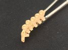
In future, I will not be buying any more Meng Magachs for their tracks, I know that much … To build it, you get a jig that holds seven links (or the end of the track you’ve already built, plus six more links), and then insert a little “comb” with six track pins. Those pins only go into one side of the track, as the links click together on the other side.

This all works well enough: the links fit together nicely and the pins are easy to insert. But the trouble starts at this point. You now need to detach the pins from the comb, but if you do that with a knife, you’ll almost certainly cut into the link, because the bits protruding to the sides stick out further than the pins do. But you can’t get cutters in, because there’s only about 2.5 mm of room between the two links, and the head of the pin takes up 0.8 mm of that.

IMG_0848.jpeg

What does work, a bit, is to hold down the links firmly and then swivel the comb up and down until fatigue in the plastic breaks the pins off, but that runs the risk that one or more of the pins will still be attached to the comb — or worse, that they come out of the track after breaking off. You have to pay close attention that all of them are in, only then throw away the comb, and then push the pins in deeper with a suitable tool. And even then, pins regularly come out. If you’re lucky you’ll find them again so you can re-insert them with tweezers — assuming they don’t go flying from the tweezers, anyway.

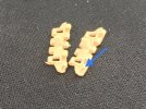
Add to this that the hole for the pin is moulded slightly short on a couple of links:

IMG_0849.jpeg

See the bit pointed out by the arrow. Inspect each link before using it, to see if it has a notch in it like that, because if it does, it won’t hold the pin at all.

101 links per side, says Meng. I’m now at fifty, and trying to think of a way to do it better. Right now I’m thinking that it may be a good idea to try and retain the pins with a drop of thick glue on top of the heads. You can’t use thin glue because that will run down inside and glue the links together.
 

Jakko

Way past the mad part
SMF Supporter
Joined
Apr 28, 2018
Messages
10,793
Points
113
First Name
Jakko
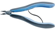
It went together surprisingly easily — I didn’t have to redo any of the parts, which is unlike the normal way of things when working with bent brass for me ;) Maybe it helps that I didn’t even try to solder them, of course. I drilled holes at both ends for the horizontal rods, and cut them clearly too long on the side that goes through the plastic card. The vertical ones I glued into holes drilled in the rear deck and also made them too long. Only once the glue had thoroughly dried, I cut them to size with my expensive cutters, which have the great advantage of making a square cut in this kind of brass rod:

lindstrom-rx-8149.jpg

And looking them up just now so I could show that picture, all I can say is: Damn! I didn’t realise they’re that expensive :smiling3: I bought them in a second-hand tool shop for something like €25 or €30 a few years ago, and thought that was quite a lot already, but they looked to be high-quality so I decided to indulge myself :smiling3:
 

Jakko

Way past the mad part
SMF Supporter
Joined
Apr 28, 2018
Messages
10,793
Points
113
First Name
Jakko
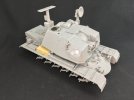
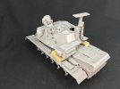
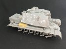
We’re approaching the painting stage:

IMG_0866.jpeg

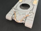
On the bow are towing cables like on the later Magach 6 en 7:

IMG_0865.jpeg

These are by EurekaXXL, but I’m not all that enamoured by them. The quality is good, but the instructions are notable mostly by the total lack of them. Only by browsing around their web site did I find some pictures of assembled cables, which finally made me understand how they’re supposed to go together. And even then, the set doesn’t fit what you see there: they appear to sell two sets for the Merkava 1 and 2 (that is: two different sets meant for both of those tanks) and one set for the Magach 6 — but going by what’s in the set I have, you get the same things in all three. You can build three or four cables from what’s supplied: two thick cables with small eyes on the ends, and two slightly thinner ones with a larger eye, that you can then also connect to make one double cable of twice the length, just oile on Centurion tanks.

I drilled out the eyes with plates in them and didn’t fix the two cables together, so that I had two to put onto the bow. Also, I used cable from Trumpeter, because it’s softer than the one supplied by EurekaXXL, making it easier to bend into the necessary curves.

The brackets on the mudguards are nothing more than a piece of 1 mm plastic rod, glued into a hole I drilled into the mudguard, with a 4 mm disc on top and then a smaller disc of 1.2 mm diameter.

The little number plate next to the hatch comes from the Meng Magach, which gives you three different ones (times two each, there’s another one on the lower rear hull).

The right-hand air cleaner has a shovel, again like the Magach:

IMG_0863.jpeg

I think the shovel is from Tamiya British infantry, the brackets for it are scratchbuilt based on those of Meng’s Magach once more.

On the left rear are two spare track links and a stretcher:

IMG_0864.jpeg

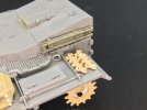
Those links are Meng too, just like the ones on the side of the turret, but I drilled them out because oddly, these aren’t moulded hollow, unlike the links for the actual tracks. The stretcher is from AFV Club. On the Magach this is carried on the left front mudguard, but that is difficult on an M48 hull because of all the supports on top of it. On the rear here is a good spot for it, if you ask me.
 
Top