SE5a CONSTRUCTION BEGINNING TO . . .

T

tigertc

Guest
Could you bomb parliament first?

Then do a tour of England taking out all the council tax offices?
 
Joined
Oct 13, 2004
Messages
611
Points
16
First Name
Grahame
At last I’ve made a start on the bomb rack, or to be accurate on the bombs; there’s no point making a bomb rack if I can’t make the bombs! Here’s a photo to show what I’m aiming for. (sorry, I just couldn’t stop myself!!)


bomb1.jpg


I decided that the only practical method is to turn the bombs, but therein lays the first problem; I’ve not got a lathe. If you work for Health and Safety I suggest you don’t read the next bit. I "converted" my vertical drill stand into a make shift lathe, very Heath Robinson but it works.


bomb2.jpg


I started with a length of curtain pole and I’ve now got the basis for one bomb, but I don’t think I would be able to produce all 4 bombs and end up with them all being the same; they’re quite a complex shape.


bomb3.jpg


I’m thinking of using this one as a master for a mould and then making a set of bombs from casting resin. I’ve never used casting resin before so any tips / advice will be gratefully received.


One question that immediately springs to mind is “is it tuff enough to withstand being dropped from the model?” They will be released quite low, I’d think about 50ft and at relatively slow speed over grass. For safety I intend to mould the front black bit from rubber and the arming vanes will be removed.
 
Last edited by a moderator:
S

smcouch77

Guest
Hey Grahame! That looks just like my lathe! I cut out a pattern using the picture above and set it against each bomb as I turned them. They're not "factory perfect" but you can get them close enough. I drop mine from about 10' over pavement with only minor scuffing of the paint. Black rubber would fix that.
 
Joined
Oct 13, 2004
Messages
611
Points
16
First Name
Grahame
There was no chance of getting any casting resin until after the Christmas holidays and as Steve successfully turned his 4 bombs I thought I might as well give it go.


I’d turned the first one using a card template and found it quite a difficult and slow job; then I had a “eureka” moment, it does happen! I measured the diameters at various points along the length of the bomb, turned the wood as a series of cylinders and then simply tapered from one diameter to the next.


bomb 3.jpg


This produced the other 3 bombs very easily and quickly; just as Steve said, “ they’re not factory perfect” but certainly near enough for me and a lot cheaper than buying casting resin etc.
 
Last edited by a moderator:
S

smcouch77

Guest
AH! Ingenuity! the mark of a true modeler.

Merry Christmas, my friend. And a happy New Year!

Steve
 
Joined
Oct 13, 2004
Messages
611
Points
16
First Name
Grahame
Making the bombs as a series of cylinders was simple and quick, which is just as well because I’ve had the make a completely new set of bombs. It wasn’t until I came to fit the rear fins that I realised that the rear section of the bombs was about ¼" too short. It just goes to once again emphasise the old adage “measure twice cut once”!


So what went wrong?


I first tried to turn the bomb using a single template of the wood to be removed, this meant that before the template for the widest part of the bomb got close to the surface the deepest cuts had to be made and this made the work piece quite weak and impossible to work with safely. I decided to “split” the bomb into 3 sections; I made templates for the front and middle sections, the rear section is just a straight taper so didn’t need a template. To ensure that the curves “flowed” nicely I decided to make the templates overlap by a ¼" but somewhere I got the measurements wrong! Having turned the front and middle sections I simply measured the overall length of the bomb and tapered the rear section accordingly not realising that the front of the bomb was in fact ¼" too long. When I decided to turn the other 3 bombs I used the master, not the photo, to set the callipers and measure the distances so duplicating the error. When I discovered the error I remounted a bomb in the lathe and tried to correct it but that didn’t work at all so 4 new bombs it had to be. It’s not all doom and gloom though; at least I now have some “spare” bombs to practice on.


I found that cutting 2 slots as a cross to fit the fins made the rear section very fragile and I was afraid that I might break the “legs”, so I cut one slot first, glued in opposing fins made from a single piece of 1/64th ply, then cut the other slot and fitted the other 2 fins once again as a single piece.


bomb 5.jpg


The bombs have been filled and sanded but I’m not too concerned about a perfect finish, after all if everything goes to plan they will be dropped from a great height and are certain to sustain damage or even get lost in the grass!


I turned a plug for the nose of the bombs from which I hope to make a mould to produce them in rubber.


bomb 4.jpg
 
Last edited by a moderator:
R

rjwood_uk

Guest
very nice work there. looks very convinsing!!!

is the hook sticking out the back the arming pin that would need to be pulled out before release?

did the SE5 have a bomb rack under it or where they just "thrown" out?
 
Joined
Oct 13, 2004
Messages
611
Points
16
First Name
Grahame
Richard


The decision to add the bombs was only taken recently after seeing the photo of Steve’s model; I’ve done very little research on the subject myself. I’m using information supplied by Steve; if it’s good enough for him then it’s good enough for me!


I’ve no idea what the loop at the back is for but I do have some general information:


The SE5a was developed well after the time of dropping hand grenades or bombs by hand from the cockpit or shooting at the enemy with a pistol. The load it could carry was limited so 4 bombs of 20lbs each was the maximum, either as 2 sets of 2 bombs, one under each wing or a rack of 4 under the fuselage just aft of the undercarriage legs. The bomb release, operated by the pilot, is the out of focus black lever mounted low down on the cockpit side.


cockpit 7.jpg


Pulling it back released a bomb, pushing it forwards reset the ratchet system, pulling it back again released the next bomb and so on until all 4 bombs had been dropped.


Grahame
 
Last edited by a moderator:
S

smcouch77

Guest
The bombs look really great! How did you do the little "lugs" around the nose piece?

I think the loop on the tail was to hang the bombs on a rack used on bombers. I have pictures with and without. The drawings I have of the rack show the bombs with loops, but they're not attached to anything.

View attachment 15903

BombWW1DSCF4195.JPG
 
B

Bunkerbarge

Guest
Now you're into a whole new area of flying Grahame, trying to drop a bomb onto a target. That should keep you busy for a few hours and probably cost you a couple of bombs.

Maybe do it in short grass first!!

Lovely modelling job as always though. When is your anticipated maiden flight? I can't wait to see this model in the air.
 
Joined
Oct 13, 2004
Messages
611
Points
16
First Name
Grahame
I don’t know about bombing a target, I’ll be happy if the bombs stay attached until I “flick the switch” and then they actually release from the model!

It makes sense that they would produce standard bombs; in the photo of them mounted in the “vertical” bomb rack you can see that they have the mounting brackets that are used on the SE5a bomb rack but they do nothing in this one.

When I turned the nose section I included the “collar” around the end, having removed it from the rest of the wood I mounted it onto a cocktail stick and made a series of slots in the collar using the Dremmel with a thin cut off disc. I cut a strip of 1/64th ply about 1/8" wide by 3" long, put it in one of the slots protruding the correct amount onto the nose section and gave it a drop of cyano, I then trimmed off the excess length and repeated the procedure. When all the lugs were in place I gave the whole lot a good “cyanoing” then sanded the lugs down to the diameter of the collar.

It sounds more complicated than it was to actually do; it had to be easy because I wasn’t going to go to too much trouble as I have serious doubts that I’ll be able to produce rubber nose sections with such fine detail.
 
Joined
Oct 13, 2004
Messages
611
Points
16
First Name
Grahame
This is a compilation of posts “lost” because of the hacker attack


I intended to make a mould for the nose section from Plaster of Paris but a trip to our local chemists drew a blank; they even tried to order some from their supplier with no luck. During a recent decorating episode, which involved a fair amount of repair work to the walls in preparation for emulsion painting, we used Polyfiller, it seemed very similar to Plaster of Paris so thought I’d try it.


The plug was prepared by dripping molten candle wax all over it, heating it up with a hot air gun re-melts the wax and most of it drips off leaving a very thin layer. I mounted it on a plastic base with a wall of Plasticine and then gave the lot a spray with WD40.


bomb 6.jpg


The Polyfiller was mixed quite thin and carefully poured in to fill the mould. It’s not as quick setting as Plaster of Paris; it took about 2 hours to harden and be ready to remove the Plasticine and the base, then another couple more to dry before carefully easing out the plug.


bomb 7.jpg


It has actually turned out surprisingly well; there are a few places where the Polyfiller has broken away in between the lugs but to be honest I expected a lot worse. It remains to be seen whether or not I can use the mould to produce acceptable rubber nose sections; I still have my doubts.


There was a reply from Alan2525 about the type of rubber


Alan


I have not idea what sort of rubber I’ve used; I bought it years ago from the model shop, I think its intended use was for making moulds for casting Plaster of Paris figurines. It’s very soft with a “natural” colour; you melt it over a low heat then pour it either into a mould or over a plug dependant upon whether you’re making a male or female item, and then just let it cool and set.


Grahame


Being thermo-plastic it was easy to “touch up” the mouldings using a precision screwdriver heated over a candle flame. They’ve been glued to a 1/64th ply base with cyano and given a coat of black paint.


bomb 8.jpg


The finished parts are not perfect but I’m not going to too much trouble as they are “throw away” parts and as such will be attached to the bombs with double-sided tape for easy replacement, I’m sure they will need replacing after just a few “bombing runs”. I might make a set of better finished parts for static display.
 
Last edited by a moderator:
S

smcouch77

Guest
Those ends look really fine! I need an extra set too. I'll make a set with this kind of end for dropping and touch up the others for static. Thanks!

Steve
 
Joined
Oct 13, 2004
Messages
611
Points
16
First Name
Grahame
An assembled bomb partly painted.


287477953c056001.jpg


I really uploaded this image to check the new “gallery”.


This is the biggest photo that can be used.


OK sorted it out now; I'd linked to the thumbnail not the full size image. Well it was new years eve!!
 
Last edited by a moderator:
Joined
Oct 13, 2004
Messages
611
Points
16
First Name
Grahame
The bomb release mechanism on the SE5a is very complex, no surprise there then! Although of course it is a proven design there is no way I could duplicate it in miniature so I’ve had to design from scratch


Steve used 4 different length pins to hold the bombs, being a control line model he was able to use a 5-way switch to control the release mechanism but I only have either the retract channel or, if I invest in a new 8 channel receiver, a proportional channel. A proportional channel would be the easiest to work with but I don’t like the idea, if I turned the knob a bit too far a bomb might almost but not completely release then with vibration it could release itself at an unplanned time, which could be dangerous, or at the very least loose me a bomb.


I will use Steve’s idea of different length pins and having decided that the “bang / bang” retract channel it will be, I need some way of “stepping” the release mechanism. I got my thinking cap on and came up with an idea inspired by the timing gear in a clock. I made a mock-up to see if it would work in practice.


The main release bar has 5 indexing pins spaced at 5mm intervals and will eventually have 4 bomb release pins each 5mm longer than the previous.


bomb release 1.jpg


The release cam has a slot cut out from the centre; before an indexing pin is released from one end plate by passing through the slot the other end plate is in a position to "catch" the next indexing pin.


bomb release 2.jpg


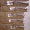
This is a series of photos showing the sequence as the servo moves the release cam arm backwards and forwards from one extreme to the other; the release bar steps by 5mm with each operation.


bomb release sequence.jpg


At the moment I’m using an elastic band, the spring tension will need to be worked out when it is actually releasing bombs, I hope!
 
Last edited by a moderator:
B

Bunkerbarge

Guest
Graham, you're obviously well on your way with this but if you decide on a differrent direction I would have a play with a model yacht sail winch. You could use that to pull in a wire that operates a slide with some sort of release mechanism attached.

The beauty of a sail winch is that you have a lot more travel to play with than you do on a normal aircraft servo.
 
Joined
Oct 13, 2004
Messages
611
Points
16
First Name
Grahame
Richard

I did consider using a “servo slower” to give me more time to play with after a bomb has been dropped, to lessen the chance of almost releasing the next, I hadn’t thought about a sail winch, which would give the same result. The problem I could see with this arrangement is that there would also be a delay after moving the servo channel control until the bomb was actually released.

Another idea I had was to buy a different control knob for the transmitter and arrange some form of indexing so I could confidently turn it a ¼ of a turn at a time.

One major drawback with both these methods is that I’d have to buy a new 8-channel receiver.

Grahame
 
Joined
Oct 13, 2004
Messages
611
Points
16
First Name
Grahame
Before I could start on the bomb rack itself I had to finish off that most useful of Christmas presents, a family size tin of Quality Street; for those who haven’t realised these tins also provide a good supply of flat tinplate. As a special favour, to help the better half keep to her new year’s resolution to watch her diet, I volunteered to take on the task myself!


The main body is made from the tinplate with a brass tube for the rear support. The release arm is made from 2mm threaded rod, the threaded section acts as the bearing in a length of tapped snake inner cyanoed in a brass tube. It will extend up into the fuselage through the large opening just behind the undercarriage legs to connect to the servo.


bomb rack 1.jpg


The release mechanism works a lot better now that a bearing supports the release arm.
 
Last edited by a moderator:
Joined
Oct 13, 2004
Messages
611
Points
16
First Name
Grahame
The bombs are now finished, not without a few problems along the way!


bomb 9.jpg


I painted the rubber nose sections with Warbirds paint; I thought it would be OK because it is water based although it does have a couple of drops of a catalyst added to make it fuel proof, but it turned sticky after a few hours so obvious there was some reaction. I stripped the paint off but the rubber was still sticky, I’d got nothing to loose so I tried the old “trick” of dusting them with talcum powder, this time I painted them with “genuine” acrylic and there was no problem, I dusted them again, just to be sure, before the second coat.


I’d intended to attach the nose sections with double-sided tape for easy replacement but this also didn’t work very well so they are now epoxied in place.


The arming vanes are from tinplate soldered to a pin so these are easily removable.


They will be removed before dropping the bombs because not only could they cause damage they would also be damaged themselves.
 
Last edited by a moderator:
Joined
Oct 13, 2004
Messages
611
Points
16
First Name
Grahame
Even this simplified bomb rack is quite complex and it still has the safety stops to be added.


bomb rack 2.jpg
 
Last edited by a moderator:
Top