I've managed some more progress on the interior.
With the main lower hull tub plates assembled and a few smaller components already added internally, in step 5 you are instructed to add the track guards. This is because both the engine firewall wings and the dividing fighting to front compartment support, slot down and trap them in place as early as step 11. I will leave them off for now to aid test fitting of the interior. Many of the internal components can be built up into small assemblies. As the instructions can skip between different areas of the interior, keeping tabs on their fixing sequencing becomes increasingly important. To make this process simpler I decided to loosely follow the instruction break down and build from the engine bay forward. I will sometimes fix parts fitted in later steps as long as they do not impede other parts, and are to be painted in the same base colour.
The engine bay is separated by the firewall panel and was painted entirely in red oxide primer. Construction of the main components in this area run from step 6 to 12 so these parts were assembled into small sub-assemblies to be painted separately. To avoid connecting the engine assemby to the radiator assembly via the stepped pipework connection (shown below in the step 12 CAD image in pink and green) I would very much recommend fitting parts L23 and L58 from step 11 directly to parts L5, L6 and L56 shown in step 9, beforehand. Not only will this prevent a possible dodgy mid pipe join but will make for a far easier final connection when both assemblies are fixed together. The newly connected parts L28 and L53 now connected to the engine pipework (see second pic below) will easily slot into the holes in the radiator assembly (part X37) shown in Step 11 (A1)


Much later in step 34 both engine cooling louvres along with part Z17 will also need a covering of red oxide so I will ensure these areas are painted with the rest of the engine bay components. The engine firewall panel will need painting red oxide on the engine bay side and Elfenbein on the fighting compartment side.
My only area of concern in the engine bay area is that the horizontal bracing panel that is incorporated into radiator moulding X37 would not locate in between the two vertical ribs on the firewall panel. It clearly shows it should (see arrow) in the CAD drawing below, but test fitting the radiator assembly to the cut outs in the port side lower plate left it nowhere near close enough! The radiator assembly has to connect to both the port side plate and the engine when final fixing inside the engine bay is made, so a little jiggery pokery will be required. Lining it all up neatly after paint will most definately require patience and a steady hand.

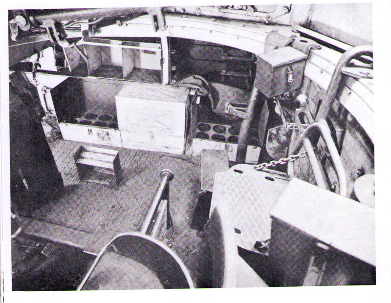
Lots of test fitting is required. Pin holes in the upper rear of the ammo boxes will require filling if visible


Moving forward into the fighting compartment Steps 13 and 14 cover components underneath the rotating turret floor. This comprises of a large riser to clear the propshaft and I presume original fuel tanks, the chequered floor plate and battery. The ammo storage boxes then sit snugly down between the riser and the starboard side plate. The single piece riser part is painted in the same red oxide colour as the floor so it can be safely fixed in position. The chequered floor plate is to be fixed over it, but as the battery and propshaft are fixed underneath, this will also be painted separately along with the assembled ammo storage boxes. The front vertical panel part Xa18 will be painted in Elfenbein, so again will be kept separate until after painting.
After test fixing the Xa18 panel, I would definitely recommend fixing the small wiring conduit part Y5 after the gearbox floor supports, (parts Xa16 & 17) are added in step 19. This part basically bridges the wiring run and slots between both sides much easier, after the parts mentioned are added.
Engine firewall panel, chequered floor plate, battery and ammo storage bins, front panel Xa18 and port side brake assembly and pipework all getting a test fitting.

All horizontal surfaces in this area will be painted in red oxide primer and the vertical panels and ammo boxes in Elfenbein. Part Y54 in step 17 was also fixed in place as this is also painted the same colour as the side plate it is attached to. Part Y16 in step 25 will also need to be added in this area so was also cleaned up ready for paint.
Only the upper shell halves are offered for these three ammo boxes and are engineered to slot into a PE rack. In step 14 there is an option to leave the shells on shows or to simply fit the lid.

As mentioned above there are solid lids for these ammo boxes provided, I am unsure if these are hinged and how you would display the ammo with the lids open. They look to hinge backwards but would interfere with components like the MG ammo pouches fixed above them (see step 33). Can anybody offer any advice for this conundrum?
David Parker's incredible 1/16 scale Ausf H fighting compartment floor with lower turret floor and vertically stored ammo does give us some clue in this area. There doesn't appear to be actual hinges on the boxes.

Moving on to the front compartment, this area has by far the most internal components. It includes the gearbox, final drives, brake assemblies and associated linkages, levers, electrical boxes, crew seating, radios, and more ammo storage. Taking reference from David Parkers build, my plan will be to assemble and fix as many parts as possible that were painted in red oxide primer, to the hull floor first. Parts such as the gearbox, the instrument panel that’s sits above it, and small electrical connection boxes will have wiring added and will be painted separately.
Starting in step 14 with the brake assemblies, these were both fully assembled and their pipework can also be safely added. The half shafts that connect to both the inner final drive mouldings Z12 and the front of the gearbox, both connect through the brake assemblies. Parts Z12 connect to the outside of the side plates so you have to figure out how best to assemble all these components if you plan to paint things separetely.
The instructions don’t make it very clear in step 14, but the brake assemblies are handed. The main circular components shown in the first sequence box of pic A4 can be assembled the same way but the starboard side levers (parts Q12 & 14) shown in the next box need to be assembled as a mirror image (see arrow below) The lower foot portion of parts Q11 and Q12 must be on the outer side of each brake assembly to locate onto the rear of the bow plate.

Another little assembly conundrum is how to assemble the two gearbox drive shafts (assembly A3 in step 15 and parts Q24 and Q41 in step 16) when they are connected to parts fixed to both inside and outside of the lower hull. They are instructed to be fixed through the brake assemblies to the inner final drive mouldings (parts Z12) in steps 15 and 16. To paint the brake assemblies off the model, I came up with my own solution. The larger portside drive shaft (assembly A3) was test fitted through the lower hull into the slot in the inner sprocket (part Z12) and then fixed just to the final drive assembly. The drive shaft parts Q24 and Q41 on the starboard side were kept separate. Shaft part Q24 is narrow enough to fit through the brake assembly from the outside so I fixed it directly to part Z12. As both drive shafts will have to connect into holes on each side of the front of the gearbox, to avoid bending painted halfshafts when it was time to fix in the gearbox I figured part Q41 could be fixed directly to part Q35 (a separate front moulding of the gearbox). Part Q35 is painted in red oxide anyway so now the main gearbox moulding can be simply added without a fight. A win, win


As all the linkages and levers in steps 17 and 18 were painted in red oxide they were carefully cleaned up, assembled, and fixed to the floor. Helpful colour coded CAD drawings assist in confirming parts placement. In step 19 the gearbox floor supports are added and as confirmed in the CAD image, the pipework from the starboard side brake assembly fits under one (part Xa17). As my brake assemblies require painting off the model, part Xa17 will now have to be fixed in place after paint too. Test fitting shows that the other floor support (part Xa21) does not impede the port side brake assembly pipework so it can safely be fixed to the floor.
All the components for the front compartment from steps 17 to 19 that are painted in red oxide have now been fixed to the hull floor. In the pics below both the brake assemblies with pipework and the gearbox are just dry fitted.


The pic below also shows the front to fighting compartment bracing support from step 26 dry fitted to test spacing for the front compartment ammo bin yet to be assembled. There are quite a few visible pin marks on this part that will require filling.

The tabs on the wings extending from both support and firewall can be seen clearly in the pic above and the reason both track gaurds are to be fitted before these two items are fixed in place. There are also some electrical components yet to be assembled from step 20 as these also require painting separately.


")
 Sprue X would have been nicer


 )
)