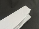
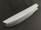
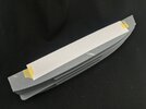
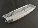
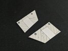
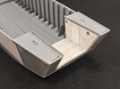
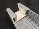
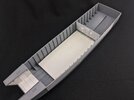
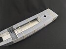
Landing Craft, Assault — Operation Infatuate I, 1 November 1944 (1:35 Gecko kit)

Jakko

Way past the mad part
SMF Supporter
Joined
Apr 28, 2018
Messages
10,950
Points
113
First Name
Jakko
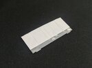
Thanks :smiling3: I decided to go for the armoured engine room bulkhead, so here’s the start of it:
IMG_9983.jpeg

This is just the back of the bulkhead part, to which I glued a sheet of 0.25 mm plastic card, trimming it to size only after doing so. I then engraved the lines to make the individual armour plates as well as the L-profile at the top, and will now need to add rivets, once I work out where they have to go :smiling3:

On the starboard side of the hull, I also scribed the planks, because I don’t think there would have been raised lines between them:

IMG_9982.jpeg

I just held a steel ruler firmly along the moulded-on lines and used a Trumpeter scriber (like the Tamiya one, but smaller). Now I only need to remove the raised ones without obliterating any detail …
 

Jakko

Way past the mad part
SMF Supporter
Joined
Apr 28, 2018
Messages
10,950
Points
113
First Name
Jakko
When working on this model tonight, I got two songs (well, song titles) in my head …


And


:smiling3:

This is a very strange model. The hull shape and size seem to be just about perfect, everything else appears to have been designed by someone working from photographs using a ruler marked in centimetres but not millimetres.

As a result, I ended up doing this:

IMG_9984.jpeg

That is, after cleaning up the scribed planks (scraping off the ridges, then running the scriber through the seams again to clean them), I removed all the bolt/rivet heads and the little ledge that indicates the outline of the armour plates on the hull sides.

The reason to go all the way there is because everything is wrong ;) Since Gecko put the steering position in the wrong place, the front edge of the armour plate is too, because the two line up. However, I then noticed in the drawings that the seams between the plates are also in the wrong places, not to mention that there are not enough seams anyway. Plus: these plates were bolted to the outside face of the hull, but Gecko has moulded the hull thickness the same for both the wood and the armour — only the little edge is thicker. So I will cut new plates from thin card, stick them to the hull, and then recreate all those nice little bolts and rivets … Because why not? ;)
 

Jakko

Way past the mad part
SMF Supporter
Joined
Apr 28, 2018
Messages
10,950
Points
113
First Name
Jakko
Turns out the rear edge of the armour is also in the wrong place — it looks like the whole armour plate is the right length, just not correctly located on the hull. Therefore, I chiselled and scraped away the rear edge better than I had when I expected it to be covered with my new plate, and extended the scribed planks a little:

IMG_9986.jpeg

Then I measured the length and height needed using a piece of paper taped to the hull, which turns out to be 250 mm long and 35 mm high. I cut two pieces like that from Evergreen 0.13 mm sheet — it should be 0.17 mm or thereabouts, but who’s going to measure? :smiling3: — and taped one to the hull:

IMG_9987.jpeg

Taking care to get it fairly tightly against the kit part, with the bottom edge right where the moulded-on edge was and the front and rear edges at frames 3 and 22. I could then run liquid cement along the top and bottom, pushing the plate down from rear to front to ensure it would conform to the hull shape. After removing the tape, I could also glue the front and rear edges, then repeat on the other side:

IMG_9988.jpeg

It’s far easier to glue them down first and only cut them to follow the line of the hull top after the glue dries, than to attempt to get that right first.
 

Jim R

SMF Supporter
Joined
Apr 27, 2018
Messages
13,835
Points
113
Location
Shropshire
First Name
Jim
So much to correct but right up your street. Excellent information on scribing. I'd never heard of a scrawker but it's a great name.
 

minitnkr

Rabble & escape committee member
SMF Supporter
Joined
Apr 27, 2018
Messages
6,746
Points
113
Location
Dayton, OH
First Name
Paul
Thats the sound my reversed blade makes when I scribe a line in plastic.
 

Jakko

Way past the mad part
SMF Supporter
Joined
Apr 28, 2018
Messages
10,950
Points
113
First Name
Jakko
Thanks all :smiling3:
There's always something to learn from your builds
And I don’t even start out intending to make it educational :smiling3:

Excellent information on scribing. I'd never heard of a scrawker but it's a great name.
Neither had I — I just have two tools that appear to have that name :smiling3: I would highly recommend getting one, BTW, if you envision yourself doing more than very small amounts of scribing lines in plastic. Far easier to use for this than a needle or a knife blade in reverse.
 

Jakko

Way past the mad part
SMF Supporter
Joined
Apr 28, 2018
Messages
10,950
Points
113
First Name
Jakko
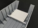
Continuing on the inside, I put a crossbar into the hull at the front of frame 3, at the correct depth to take the rear end of the front floor (taking into account the thickness of the plastic I was going to use). Then I made floor from 1 mm plastic card, scribing eight planks (rather than ten like Gecko’s floor) and filed the front and rear edges to fit into the hull before glueing it in place:

IMG_9990.jpeg

It’s too wide on purpose, but in retrospect it would probably have been better to make it the correct width (39 mm) and have the side walls extend below the floor.

Those side walls were made next:

IMG_9991.jpeg

The main reasons for doing so were that I had made the floor wider, but mainly because the ventilators (the little round thingies) are on the surface when they should be recessed. I scribed the planks (4.5 mm wide) before punching the holes for the ventilators, and then added the inspection hatches and the bits of strip to which the pulleys for the bow ramp will be attached later.

With the ventilators cut from the kit parts and glued in place:

IMG_9992.jpeg

And the bow with the walls and decks in place:

IMG_9993.jpegIMG_9994.jpeg

I shortened the decks by sawing off the part that stuck behind frame 3 before gluing everything in place.
 

Waspie

SMF Supporter
Joined
Mar 13, 2023
Messages
2,645
Points
113
Location
Portland - Dorset
First Name
Doug
I have to admit I understand little of the technical 'stuff'. But I am in awe of the detail and lengths you go to Jakko to achieve the perfect representation.
 

Jakko

Way past the mad part
SMF Supporter
Joined
Apr 28, 2018
Messages
10,950
Points
113
First Name
Jakko
I probably wouldn’t normally go to these lengths, but, well …


:smiling3:
 

Tim Marlow

Little blokes aficionado
SMF Supporter
Joined
Apr 27, 2018
Messages
16,861
Points
113
Location
Somerset
First Name
Tim
Jakko, you have some work on your hands there... I can see the end of your build - "Here is the box it came in - and here is the model I scratch built..."
Some great work going on here, seat drawn up and tea and biscuits on hand.
At least if you scratchbuild it all the resulting issues are yours alone ;)
 

Jakko

Way past the mad part
SMF Supporter
Joined
Apr 28, 2018
Messages
10,950
Points
113
First Name
Jakko
you have some work on your hands there... I can see the end of your build - "Here is the box it came in - and here is the model I scratch built..."
Almost, yeah … But at least I can use most of the detail parts that are hard to scratchbuild :smiling3: Though I can still go, “Here is the box it came in, and it’s filled to capacity with the parts I had left over.”

Some great work going on here, seat drawn up and tea and biscuits on hand.
Thanks :smiling3:
 

Jakko

Way past the mad part
SMF Supporter
Joined
Apr 28, 2018
Messages
10,950
Points
113
First Name
Jakko
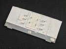
Engine room bulkhead fitted with armour plate, as well as a correct size of door and steps:

IMG_0035.jpeg

The only parts from the kit are the bulkhead and the four door handles … and I’m not sure the latter are correct, but I didn’t feel like scratchbuilding four that look like some I’ve seen in a photograph.

Making that, though, this happened:

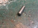
IMG_0033.jpeg

That’s a 0.6 mm domed punch from RP Toolz, which broke part of the way through making the rivets for the bulkhead :sad: This is why some are domed and the rest are flat, but nothing to be done about that. At least flat rivets are quicker to put on, because you don’t have to peer at them to see which side should go outward :smiling3:

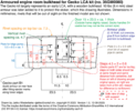
I made this drawing to show basic size and details:

LCA engine room bulkhead armour 1.0.png

No guarantees these dimensions are absolutely accurate, as some were deduced from measurements taken in photographs, which I couldn’t always fit to dimensions taken from the drawings.

BTW, I have the impression Gecko got the door basically right in terms of size, but mistook the size of the opening for that of the door itself. Pictures show that the door is bigger than the opening, to provide a good seal of course — which is also why there are no rivets in the drawing alongside the door: those are covered by it.

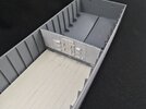
And in the hull:

IMG_0036.jpeg

I first glued the floor in place with tube cement, because of the difficulty of getting liquid cement underneath it, and weighed it down with two pots of that liquid cement to firmly press it onto the ribs in the hull:

IMG_0037.jpeg

And with the deck temporarily in place:

IMG_0038.jpeg

This because the bulkhead has little tabs at the top that locate in recesses on the underside of the deck, so it’s best to get those lined up correctly too.
 

Jakko

Way past the mad part
SMF Supporter
Joined
Apr 28, 2018
Messages
10,950
Points
113
First Name
Jakko
Thanks :smiling3: Making the drawing took about as long as making the part …
 
Top