Landing Craft, Assault — Operation Infatuate I, 1 November 1944 (1:35 Gecko kit)

Jakko

Way past the mad part
SMF Supporter
Joined
Apr 28, 2018
Messages
10,837
Points
113
First Name
Jakko
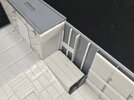
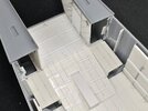
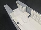
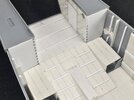
Thanks, though it’s slower going than I would like (which is, of course, entirely my own fault :smiling3: ). But by now I’ve made more of the floor and the rear walls of the forward compartments:
IMG_0095.jpeg

Gecko has made the “tunnel” far too small, because their version doesn’t “climb” up the sloping floor but is flat together with the centre bench. But because the bench really follows the curve of the main floor, and the tunnel is an extension of the bench, it ends up much further up the sloping floor here than it does in the kit.

I made that part by cutting an almost-square of plastic card and then cutting a slot for the tunnel down the middle. That way, I didn’t have to work out the size of two triangles for the sides and cut them accurately — I could just build a rectangular block of sides, top and rear to glue into the slot, then fill the gaps that were left.

Similarly, for the side floors, I glued rectangles to the sides of the sloping floor and stuck floors for the steering shelter and machine gun cockpit on top of those. Their tops need to be at the same height as the tops of the wider parts of the frames here.
 
Last edited:

Jakko

Way past the mad part
SMF Supporter
Joined
Apr 28, 2018
Messages
10,837
Points
113
First Name
Jakko
I certainly hope it’ll be worth it in the end, though I doubt anyone will notice if I don’t show them the photos of the work involved :smiling3:

Now I need to add a bunch of details like angle iron, rivets, wooden beams and other stuff inside the steering shelter and machine gun cockpit, because trying that once the rear plates are on will be very difficult.
 

Jakko

Way past the mad part
SMF Supporter
Joined
Apr 28, 2018
Messages
10,837
Points
113
First Name
Jakko
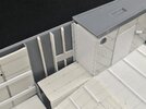
IMG_0096.jpegIMG_0097.jpeg

I can only take those rivets in small doses, so this is it for tonight, I think. No idea how Mike ever finished those Centurion bridge sections without going completely mad :smiling3:

Oh, and I replaced the moulded-on frames because as I mentioned before, Gecko’s are 1 mm too shallow. Easier to cut them off and put a bit of 3 mm strip in their place than to try and make them deeper.
 

scottie3158

SMF Supporter
Joined
Apr 27, 2018
Messages
12,722
Points
113
Location
Spalding
First Name
Paul
Jakko,
not only is your attention to detail second to none, but it's your problem solving skills that impress.
 

Jakko

Way past the mad part
SMF Supporter
Joined
Apr 28, 2018
Messages
10,837
Points
113
First Name
Jakko
Cheers, I never realised that might impress people, though … I just think about things, try something, and muddle through :smiling3:
 

Jakko

Way past the mad part
SMF Supporter
Joined
Apr 28, 2018
Messages
10,837
Points
113
First Name
Jakko
I’m not overly happy just now:

IMG_0098.jpeg

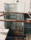
When I was building all the stuff from the last photos, I was wondering why the pieces of angle iron with the rivet heads were not up against the hull, but as I was following this photo:

LCA Arro.jpg

… I saw no reason to not have it like that. Trying to work out what is supposed to be between them and the hull, I took a close look at the plans, and found there is supposed to be nothing between angle iron and hull …

Looking at the photo again, the penny dropped and I realised why there is a gap in the photo: that plank with the metal bracket on it, that I had represented by a piece of plastic card between the angle iron and the hull, is not a plank attached to the inner face of the hull at all :sad: Rather, it’s a plank that’s been pushed inward, or maybe the ones above and below have been pushed out …
That meant the angle irons and planks had to come out again, and trying to do that, I cut through the thin plastic card I had glued to the front bulkheads to represent the armour plating. This then necessitated taking those off, but they were fully glued to the thicker card I had used to close the openings, so it all had to come out. The small ribs I had added from square rod also turned out to be of a material that’s barely glueable with model cement (I’m guessing it’s HDPS) so they just snapped off and left no more than a glue shadow behind.

Dammit.

I don’t feel like rebuilding all of this tonight, so I’ll contend myself with filling the scars left by this demolition work and probably continue tomorrow instead :sad:
 

Jim R

SMF Supporter
Joined
Apr 27, 2018
Messages
13,750
Points
113
Location
Shropshire
First Name
Jim
That's a real shame Jakko. It all looked so good. Your ability to interpret these photos has come back to bite you on this occasion. I have no doubt you'll sort it.
 

Jakko

Way past the mad part
SMF Supporter
Joined
Apr 28, 2018
Messages
10,837
Points
113
First Name
Jakko
It’s really just a matter of doing it all again, minus the horizontal planks on the hull sides. The annoyance is at having to do the same work twice, which I don’t enjoy :smiling3:
 

Jakko

Way past the mad part
SMF Supporter
Joined
Apr 28, 2018
Messages
10,837
Points
113
First Name
Jakko
Part of the way there:

IMG_0103.jpeg

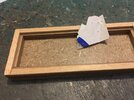
I didn’t add thicker plates behind the armour now, because I went for thicker armour plates :smiling3: I had used 0.13 mm for the first version, but that’s too thin, really — the real thing would be about 0.18 mm thick, and plastic card generally comes in 0.13 mm and 0.25 mm, both of which are about the same amount off, but the 0.25 mm is much stronger.

Anyway, I cut pieces to size and added the rivets along the inboard edge. Those are blue because of a comment on another forum, where somebody said I should paint them before cutting them off, to easily tell the domed side from the one that needs to be glued, apparently under the impression I was using moulded rather than punched rivets. That gave me the idea of colouring one side of the plastic I used with a blue marking pen:

IMG_0102.jpeg

As you can see (if you look carefully) it’s now much easier to spot the rivets that are upside-down.

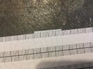
And here’s my rivet spacer in action:

IMG_0099.jpeg

:smiling3:
 

Jakko

Way past the mad part
SMF Supporter
Joined
Apr 28, 2018
Messages
10,837
Points
113
First Name
Jakko
I must say it makes things a lot easier for domed rivets. It’s not needed for flat ones, as you can stick them down either way up anyway.

Oh yeah, forgot to mention that I also remade the small ribs, by sticking two pieces of 1 × 0.5 mm strip together to get 1 mm square. Also, if you’re building an LCA without the buoyancy aids between the frames, you need to add one of these halfway between every pair of frames.
 

Jim R

SMF Supporter
Joined
Apr 27, 2018
Messages
13,750
Points
113
Location
Shropshire
First Name
Jim
That gave me the idea of colouring one side of the plastic I used with a blue marking pen:
Another one for my little book of good ideas. My RP Toolz rivet maker goes down to 0.6mm and at that size it's very hard to identify the domed side.
Glad to see you getting back to where you started :thumb2:
 

Jakko

Way past the mad part
SMF Supporter
Joined
Apr 28, 2018
Messages
10,837
Points
113
First Name
Jakko
Another one for my little book of good ideas. My RP Toolz rivet maker goes down to 0.6mm and at that size it's very hard to identify the domed side.
Mine goes to 0.5 mm, because I bought a normal punch-and-die set of theirs and then some loose “spare” punches (as I recall, they were all of €3 each!) to save on the expense of a full set that would come with a die plate you don’t actually need if you already have one. However, as I showed earlier in this thread, I broke my 0.6 mm domed punch :sad: And RP Toolz doesn’t sell direct anymore, I found out some time ago, so I also can’t just order a replacement from them.

Glad to see you getting back to where you started :thumb2:
I kind of have to, don’t I? :smiling3:

With so much having to make yourself, it does beg the question why doesn't the kit manufacturer look at the detail?
That’s the eternal question … You would kind of expect manufacturers to do their research, but it seems they did it only partly here and guessed at the remaining details. I must note here that much of the research shown in this thread isn’t mine but comes from someone else who has much more of an interest in landing craft than I do. However, if he can work all of this out, and I can interpret a bunch of things he didn’t spot too, I would expect Gecko to be able to do that too. A lot of this kit comes across as, well, lazy, though. Missing the fact that the floor curves up, I can sort of see — the drawings are not all that easy to read (but then, I would think people making CAD drawings for kits can read drawings …) — or mistaking the size of the door opening for the size of the door itself, OK. But there is no reason I can see for things like the steering shelter being in the wrong place: it lines up with the frames! How hard can that be to get right, especially since the locations of the frames themselves are spot-on?
 
Last edited:
Top