The HobbyBoss 1/32 B24D Liberator.

BarryW

SMF Supporter
Joined
Jul 23, 2011
Messages
5,043
Points
113
Location
Dover
First Name
Barry
Work has progress on the internals but before I can close her up there is a lot more fitting work to do.

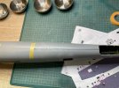
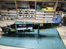
First a dry fit of the two fuselage sides without the full internals fitted. I must get that fitting perfect before I even start to work on getting the rest into place.

IMG_7116.jpeg
As you can see there is a gap from the yellow tape back towards the back. This won’t push closed so I have some work to ‘reduce’ what’s stopping it from closing. The fit underneath and forward of that point is perfect.

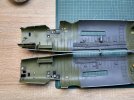
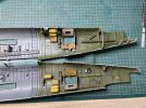
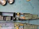
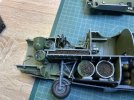
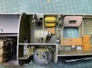
Here are the two fuselage internals side by side.
IMG_7117.jpeg
IMG_7118.jpeg

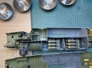
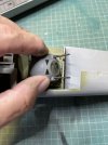
Here is a pic of the main internal structure just loosely placed into position.
IMG_7119.jpeg
IMG_7120.jpeg
I have no doubt that given how much is being fitted inside that there will be a lot of work in this.

All in all before I can cement the two halves together I need to do the following.
1/ Sort out the fit of the two fuselage sides without the internal structure.
2/ Fit the internal structure and adjust it.
3/ Before cementing the internals I need to check the fit of the rear turret and ball turret to make sure I can fit them after joining the fuselage sides. If not I will have to work out what to do to make painting easier. I believe at least as far as the rear turret is concerned that it will be OK after.
4/ I will then, with the internals loosely in place need to check how I can put at least 300g of ballast on the nose. I have a few ideas but may need to make some preparation before cementing the internals.
5/ Only then I can, carefully, cement the internal structure into place.
6/ Fit the ballast. The instructions say 300g but I see that as a minimum as it’s essential that the model is secure on its tricycle u/c given how it will be placed on my shelves.
7/ cement the sides together and check again for rear and ball turret fit.

A lot of work to do to that point.
 

Gern

'Stashitis' victim
SMF Supporter
Joined
May 17, 2009
Messages
9,708
Points
113
Location
Stourbridge
First Name
Dave
300 gm! That's a LOT of weight. Methinks that metal u/c set you got is going to save you a lot of heartache!
 

BarryW

SMF Supporter
Joined
Jul 23, 2011
Messages
5,043
Points
113
Location
Dover
First Name
Barry
300 gm! That's a LOT of weight. Methinks that metal u/c set you got is going to save you a lot of heartache!
True. But to play safe I will still use at least 300g as well.
 

tr1ckey66

SMF Supporter
Joined
Mar 6, 2009
Messages
3,686
Points
113
First Name
Paul
The Liberator is looking fantastic Barry. As you say, there’s plenty of work to do before the fuselage comes together, but the internals are looking top notch.
All the best
Paul
 

Jim R

SMF Supporter
Joined
Apr 27, 2018
Messages
13,787
Points
113
Location
Shropshire
First Name
Jim
Looking good Barry. Looks like you'll be dry fitting for quite a while. Getting that weight in will take some figuring out.
 

BarryW

SMF Supporter
Joined
Jul 23, 2011
Messages
5,043
Points
113
Location
Dover
First Name
Barry
Getting enough weight into the front is a definite challenge.

I wanted as much of the weight as far forward as possible.

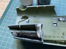
I used two part Milliput to seal the front and end of a cavity on the starboard side, then I used Gator Grip to push in and around the dry Milliput to make sure there was a tight seal.
I then poured liquid gravity into the cavity and sealed that with superglue.
After that I used masking tape to create a wall into which I poured more liquid gravity in which was again sealed with superglue.

Then, after removing the tape, I did some test fitting to make sure nothing impeded the fit of the port fuselage and it was fine.

Next step was to put in another Milliput barrier which will enable me to pour more liquid gravity in once the fuselage is closed. A m other test fit, before the Milliput was dry and that job is done.

IMG_7130.jpeg

Above you can see how it is left, for now. There will be some painting needed where the Milliput will be visible.

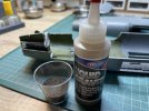
This photo below is how much LQ still need to be fitted, a full bottle plus what’s in the shot glass.

There is one large cavity which should take a fair bit over the nose wheel once the internal structure is fitted, but I will still have a lot more to get in. I have some ideas on that.
image.jpg
 

Gern

'Stashitis' victim
SMF Supporter
Joined
May 17, 2009
Messages
9,708
Points
113
Location
Stourbridge
First Name
Dave
Is there any room in the engine cowlings? I know it won't provide as much balance as the front but it may help.
 

Jakko

Way past the mad part
SMF Supporter
Joined
Apr 28, 2018
Messages
10,892
Points
113
First Name
Jakko
Replace this all with roofing lead cut and hammered into shape, then pour the Liquid Gravity in the gaps left? A while ago we discovered that Liquid Gravity has only about half (IIRC) the specific gravity of lead, so even though you won’t be able to get lead into all the corners that you can get that, it will give you about twice the weight in the same space.
 

Dave Ward

Still Trying New Things
SMF Supporter
Joined
Apr 27, 2018
Messages
8,685
Points
113
Location
South Gloucestershire
First Name
David
Getting enough weight into the front is a definite challenge.

I wanted as much of the weight as far forward as possible.

I used two part Milliput to seal the front and end of a cavity on the starboard side, then I used Gator Grip to push in and around the dry Milliput to make sure there was a tight seal.
I then poured liquid gravity into the cavity and sealed that with superglue.
After that I used masking tape to create a wall into which I poured more liquid gravity in which was again sealed with superglue.

Then, after removing the tape, I did some test fitting to make sure nothing impeded the fit of the port fuselage and it was fine.

Next step was to put in another Milliput barrier which will enable me to pour more liquid gravity in once the fuselage is closed. A m other test fit, before the Milliput was dry and that job is done.

View attachment 492179

Above you can see how it is left, for now. There will be some painting needed where the Milliput will be visible.

This photo below is how much LQ still need to be fitted, a full bottle plus what’s in the shot glass.

There is one large cavity which should take a fair bit over the nose wheel once the internal structure is fitted, but I will still have a lot more to get in. I have some ideas on that.
View attachment 492180
Front of the inboard engine nacelles? Not as big as a lever arm as the nose, but quite a large diameter for washers/coins?
Dave
 

BarryW

SMF Supporter
Joined
Jul 23, 2011
Messages
5,043
Points
113
Location
Dover
First Name
Barry
I cannot do more with the ballast until the internal structure is cemented firmly in place. So I move on to look at how the ball turret fits.

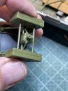
First of all it is clear that I have to fit the ball turret before I close up the fuselage and also the pin that fixes the ball turret into the roof location is far too weak and may not survive the build. IMG_7131.jpeg

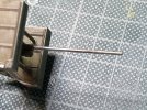
So I cut off the pin and cut a pieces of 1.5mil copper tube to a length slightly longer than the pin I removed. I also drilled a 1.5mil hole to glue the pin to the turret assembly, the other end will fit into the attachment cemented to the roof.
IMG_7132.jpeg

Some superglue and that’s done
IMG_7133.jpeg

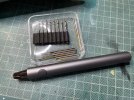
This is where I really appreciate the Wow Stick as the drilling of the hole is so much easier than doing it by hand. Even a Dremel is not as handy and easy to use as the Wow Stick. It’s perfect for models and I use it on every kit, multiple times.
IMG_7134.jpeg

Next I need to check the rear turret.
 

BarryW

SMF Supporter
Joined
Jul 23, 2011
Messages
5,043
Points
113
Location
Dover
First Name
Barry
After lots of dry fitting and adjustment I have now been cementing the internal structure firmly into place. I am happy that the two fuselage sides will fit well together. There will be a fair bit of work on the long seams to do.

I have been working in sections using clamps and have now got towards the rear. I will leave it now for a day or two before fitting more ballast.

IMG_7150.jpeg

When I am happy with the ballast I will then fit the ball turret before cementing the sides together.
 

BarryW

SMF Supporter
Joined
Jul 23, 2011
Messages
5,043
Points
113
Location
Dover
First Name
Barry
Using cut down bombs and fuel tanks to hold ballast. I have fitted around 350grams of weight which, on top of the metal nose wheel leg, should be enough, once I have added another 30-40 grams in a void under the nose once the fuselage has been closed up. This compares to 300g recommend by HB. Why more? Because the 300g are indicated in the instructions to go in front of the instrument panel. Bearing in mind the glass nose, that would take up a lot more of the nose cavity making it even more noticeable through the transparency. There is no ideal solution to this but I decided to have over half the weight further back, as you can see which means more weight overall. I estimate that the amount of ballast in total, will be over 400g. If that turns out not to be enough I will have the front of the engine nacelles left and, as a last resort, I could shove more into the nose before attaching the nose transparency. I hope that won’t be necessary.

I did consider lead weights instead of liquid gravity as it is somewhat denser, meaning less material being needed. However the density difference would be offset by voids and packing it all in the nose would almost certainly bring it further forward making it more visible. For that reason I decided that there was nothing to be gained and went ahead as I have.
IMG_7157.jpeg
It doesn’t look great but will hardly notice when done.

I have also dry fitted the ball turret. You can see below how its only attachment will be the brass tube superglued into a location point set in the roof.
IMG_7153.jpeg
It is very precarious
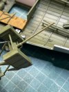
Below you can see how the guns need to be lined up with some notches as it won’t swivel.
IMG_7155.jpeg
Once the fuselage halves are joined I will have a panel to thread under the guns while trying to get four long pins inside and locate into holes that I won’t be able to see. I suspect those pins will have to be cut off.
IMG_7156.jpeg

All in all it’s a very tricky operation to do.
 

Jim R

SMF Supporter
Joined
Apr 27, 2018
Messages
13,787
Points
113
Location
Shropshire
First Name
Jim
Well done with the weight, I reckon you've got as much in as possible. Certainly very fiddly to assemble and rather fragile.
 

Andy the Sheep

SMF Supporter
Joined
Apr 7, 2019
Messages
1,551
Points
113
Location
North Eastern Italy
First Name
Andrea
A very tricky ball turret engineering from HB, indeed.
I'm pretty sure you'll end up with a fabulous result, as always, Barry.
400 g of ballast... it's impressive! It's the equivalent of pasta for 4 helpings!:tongue-out3::hungry::upside:
 
Top